

Student Learning Objectives
Lessons / Lecture Notes
Important Equations
Example Problems
Applets and Animations
Student Learning Objectives
Lessons / Lecture Notes
The Physics Classroom (conceptual)
PY106 Notes from Boston University (algebra-based):
Physics 2B notes from Dr. Bobby W.S. Lau (algebra-based)
HyperPhysics (calculus-based)
Physics 4B notes from Dr. Bobby W.S. Lau (calculus-based)
Important Equations (for algebra-based Physics)
|
|
|
Example Problems
Example Problems for algebra-based physics (from College Physics 2nd Edition by Knight, Jones, and Field):
Example Problems (Current and Resistance)
Solutions to Example Problems (Current and Resistance)
Example Problems for calculus-based physics (from Fundamentals of Physics 9th Edition by Halliday, Resnick, and Walker):
Example Problems (Current and Resistance)
Solutions to Example Problems (Current and Resistance)
| Battery Voltage | 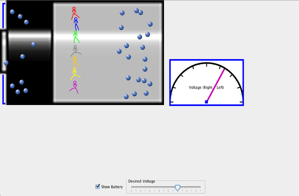 |
A simple DC circuit has a DC voltage source lighting a light bulb. Also shown is a hydraulic system in which water drives a turbine. The two systems are shown to be similar. |
| Resistance in a Wire | 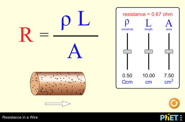 |
Observe changes to the equation and wire as you play with the resistivity, length, and area sliders. |
| Resistance in a Wire | 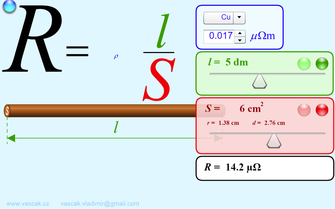 |
Another applet where you can observe changes to the equation and wire as you play with the resistivity, length, and area sliders. |
| Conductivity | 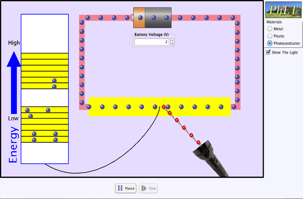 |
Experiment with conductivity in metals, plastics and photoconductors. See why metals conduct and plastics don't, and why some materials conduct only when you shine a flashlight on them. |
| A Battery | 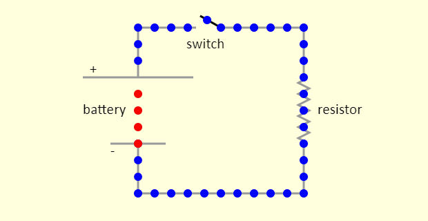 |
The simulation shows a simple circuit, with a battery, a switch, a resistor, and a few wires. Conventional current shows the Ben Franklin view of the circuit, that the flowing charges are positive (shown in red). In actuality, the flowing charges in the circuit outside the battery are negative (shown in blue) - they are electrons - while the ones inside the battery are positive. For the "Actual" situation, note what happens at the two terminals of the battery. This looks a bit like magic, but is actually chemistry. |
| Battery-Resistor Circuit | 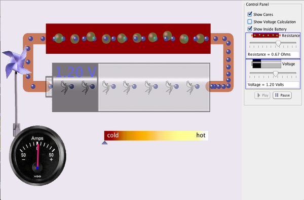 |
Look inside a resistor to see how it works. Increase the battery voltage to make more electrons flow though the resistor. Increase the resistance to block the flow of electrons. Watch the current and resistor temperature change. |
| Ohm's Law | 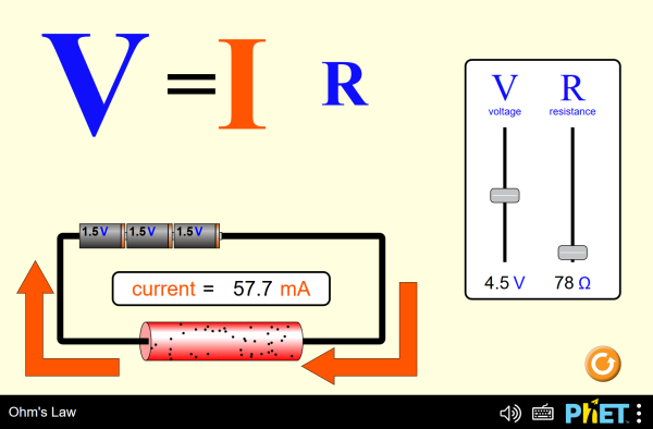 |
See how the equation form of Ohm's law relates to a simple circuit. Adjust the voltage and resistance, and see the current change according to Ohm's law. |
| Investigating Ohm's Law | 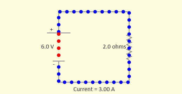 |
In this simulation, you can visualize the charge flow around a circuit, and see what happens when the battery voltage or the resistor resistance is changed. |
| Ohm's Law |
 |
Nice animation showing Ohm's Law. |
| Investigating Ohm's Law | 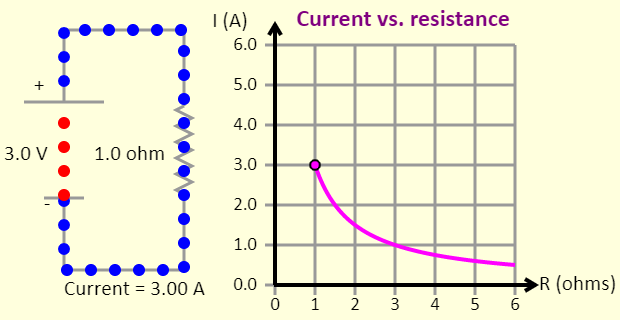 |
In this simulation, you can visualize the charge flow around a circuit, and see what happens when the battery voltage or the resistor resistance is changed. You can also sketch a current vs. resistance graph for a given voltage, by choosing a voltage and then using the resistance slider to cover the full range of resistances. |
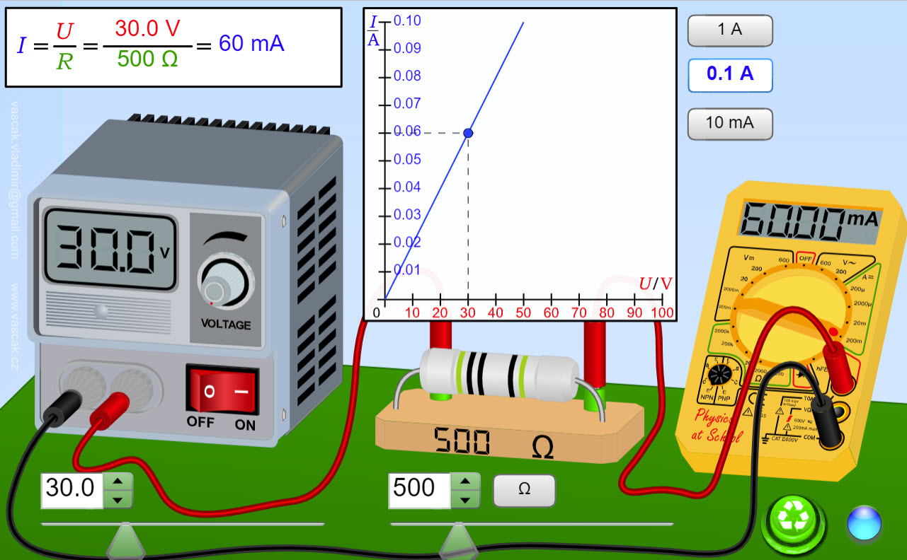
| Ohm's Law |
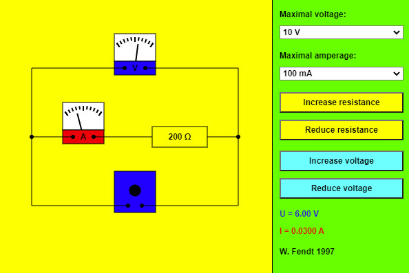 |
This app shows a simple circuit containing one resistor. In addition there is a voltmeter (parallel to the resistor) and an ammeter (in series with the resistor). You can select the maximum voltage and maximum amperage values tolerated by the meters by using the choose boxes. If you see the warning "Maximum exceeded!", you will have to choose an adequate measuring range. Resistance and voltage can be changed with the four buttons. The values of voltage (U) and amperage (I) are indicated on the bottom right. |
| Power Boxes |
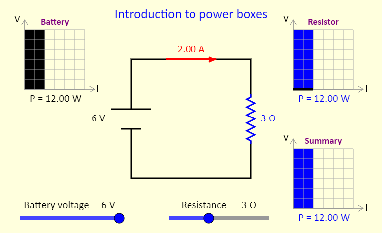 |
This simulation aims to acquaint you with the concept of power boxes, as introduced in a September 2018 article in The Physics Teacher, by Daryl McPadden, Jason Dowd, and Eric Brewe, titled "Power Boxes: New Representation for Analyzing DC Circuits". Note that one way to calculate power is to multiply the voltage and the current. In this simulation (and others below), the voltage is plotted on the vertical axis and the current on the horizontal axis, meaning that the rectangular area shown in the power box represents the power for that particular circuit element. This simulation shows the power boxes for a very simple case - a circuit with a single battery and a single resistor. At the top left, the black region on the power box shows the power input to the circuit by the battery. At the top right, the blue region shows the power dissipated as thermal energy and/or light by the resistor / light bulb. Note the thick black line at the bottom of that power box, to indicate that there is still a current in the bottom wire in the circuit, even though the voltage has dropped to zero after the current has passed through the resistor. The power box at the bottom right is a summary for the circuit. Adjust the sliders, to see the impact on the power boxes of adjusting the battery voltage and the resistance of the resistor. Once you are comfortable with this simulation, move on to see the power boxes representation for more complicated circuits. |