

Student Learning Objectives
Lessons / Lecture Notes
Important Equations
Example Problems
Applets and Animations
Student Learning Objectives
Lessons / Lecture Notes
The Physics Classroom (conceptual)
PY106 Notes from Boston University (algebra-based):
Physics 2B notes from Dr. Bobby W.S. Lau (algebra-based)
HyperPhysics (calculus-based)
Physics 4B notes from Dr. Bobby W.S. Lau (calculus-based)
Important Equations (for algebra-based Physics)
|
|
|
Example Problems
Example Problems for algebra-based physics (from College Physics 2nd Edition by Knight, Jones, and Field):
Example Problems (Circuits)
Solutions to Example Problems (Circuits)
Example Problems for calculus-based physics (from Fundamentals of Physics 9th Edition by Halliday, Resnick, and Walker):
Example Problems (Circuits)
Solutions to Example Problems (Circuits)
| Battery-Resistor Circuit | .png) |
Look inside a resistor to see how it works. Increase the battery voltage to make more electrons flow though the resistor. Increase the resistance to block the flow of electrons. Watch the current and resistor temperature change. |
| Signal Circuit | 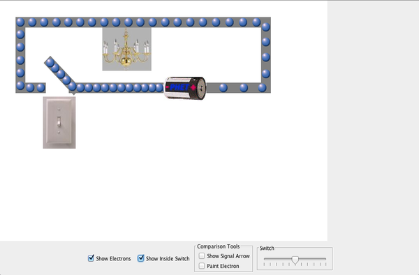 |
Why do the lights turn on in a room as soon as you flip a switch? Flip the switch and watch the electrons. Does the light turn on immediately? Explain using your observations of the model. |
| Circuit Construction Kit (AC/DC) - Virtual Lab | 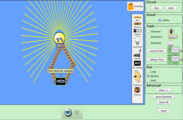 |
Build circuits with capacitors, inductors, resistors and AC or DC voltage sources, and inspect them using lab instruments such as voltmeters and ammeters. |
| Circuit Construction Kit (AC/DC) | 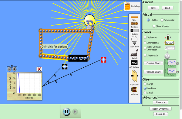 |
This new version of the CCK adds capacitors, inductors and AC voltage sources to your toolbox! Now you can graph the current and voltage as a function of time. |
| Simple Electric Circuits Simulation | 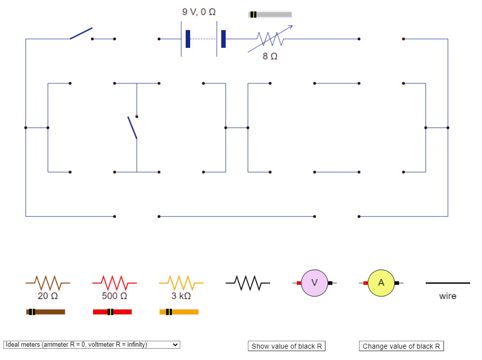 |
This great simulation allows you to build simple resistor circuits. |
| Power Boxes - Series Circuit | 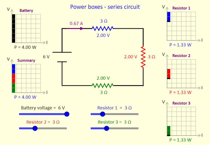 |
This simulation shows power boxes for a series circuit. The concept of power boxes was introduced in a September 2018 article in The Physics Teacher, by Daryl McPadden, Jason Dowd, and Eric Brewe, titled "Power Boxes: New Representation for Analyzing DC Circuits". This simulation shows the power boxes for a circuit with three resistors in series. At the top left, the black region on the power box shows the power input to the circuit by the battery. On the right, we see (individually) the power dissipated as thermal energy and/or light by the three resistors / light bulbs. Note the thick black line at the bottom of those power boxes, to indicate that there is still a current in the bottom wire in the circuit, even though the voltage has dropped to zero after the current has passed through the resistor. The power box at the bottom left is a summary for the circuit, showing where the power in the circuit is dissipated. Adjust the sliders, to see the impact on the power boxes of adjusting the battery voltage and the resistances of the resistors. |
| Power Boxes - Parallel Circuit | 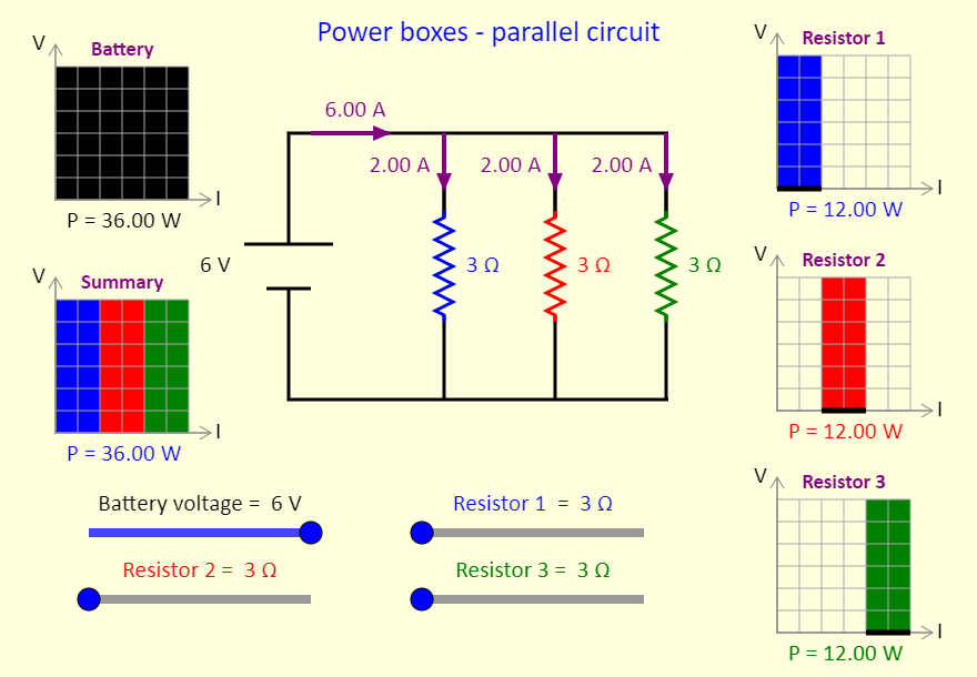 |
This simulation shows power boxes for a parallel circuit. The concept of power boxes was introduced in a September 2018 article in The Physics Teacher, by Daryl McPadden, Jason Dowd, and Eric Brewe, titled "Power Boxes: New Representation for Analyzing DC Circuits". This simulation shows the power boxes for a circuit with three resistors in parallel. At the top left, the black region on the power box shows the power input to the circuit by the battery. On the right, we see (individually) the power dissipated as thermal energy and/or light by the three resistors / light bulbs. Note the thick black line at the bottom of those power boxes, to indicate that there is still a current in the bottom wire in the circuit, even though the voltage has dropped to zero after the current has passed through the resistor. The power box at the bottom left is a summary for the circuit, showing where the power in the circuit is dissipated. Adjust the sliders, to see the impact on the power boxes of adjusting the battery voltage and the resistances of the resistors. |
| Combinations of Resistors | 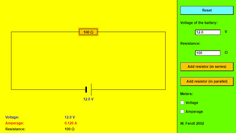 |
Nice and simple applet that lets you build many different combination resistor circuits. |
| Power Boxes - Combination Circuit |
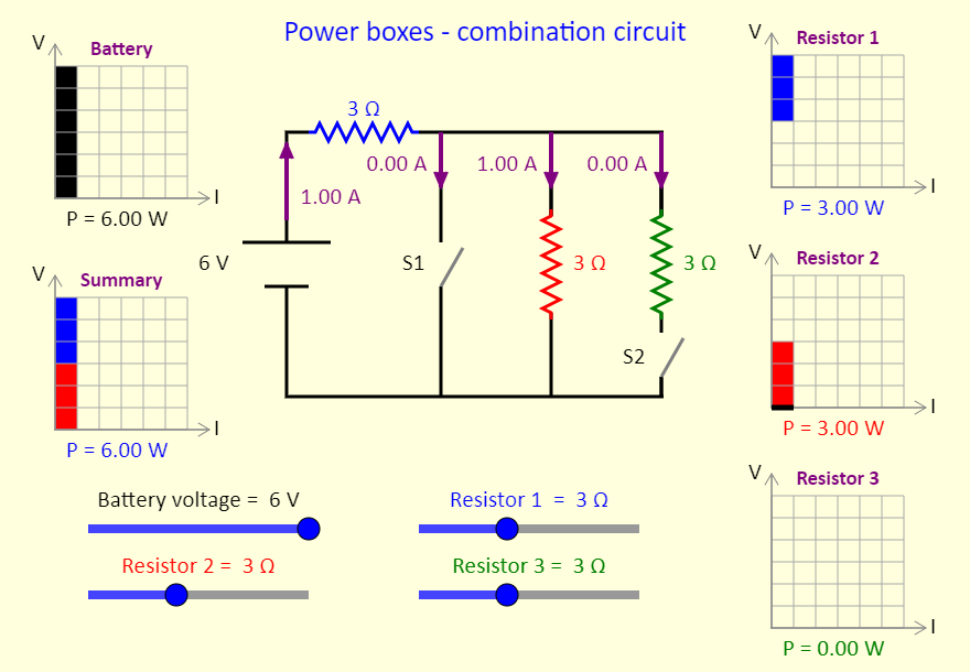 |
This simulation shows power boxes for a circuit that can have resistors in series and parallel, depending on the switches. The concept of power boxes was introduced in a September 2018 article in The Physics Teacher, by Daryl McPadden, Jason Dowd, and Eric Brewe, titled "Power Boxes: New Representation for Analyzing DC Circuits". This simulation shows the power boxes for a circuit with three resistors and two switches. When switch 1 is closed, that branch has zero resistance and all the current flows through switch 1, with no current going to resistor 2 or resistor 3. Things are more interesting when switch 1 is open. In this case, try setting all the resistors to the same resistance, and then predict what will happen when switch 3 is closed. In particular, predict what will happen to resistor 1 (the blue one). At the top left, the black region on the power box shows the power input to the circuit by the battery. On the right, we see (individually) the power dissipated as thermal energy and/or light by the three resistors / light bulbs. Note the thick black line at the bottom of those power boxes, to indicate that there is still a current in the bottom wire in the circuit, even though the voltage has dropped to zero after the current has passed through the resistor. The power box at the bottom left is a summary for the circuit, showing where the power in the circuit is dissipated. Adjust the sliders, to see the impact on the power boxes of adjusting the battery voltage and the resistances of the resistors. In addition, use the buttons to open or close the switches. |
| Two/Three Way Switch | 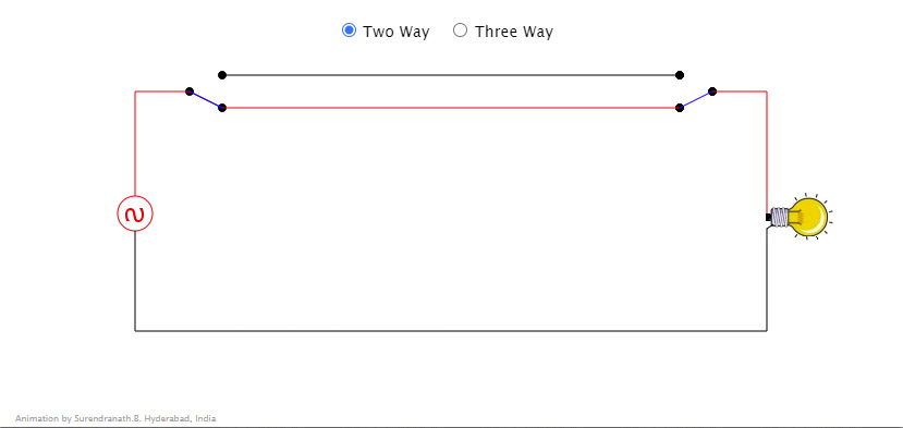 |
Click near the switches to change the connection. Three Way switching is done using a cross over switch. Clicking near the crossover switch changes the connections. Many such crossover switches can be used to operate a device from various locations. Notice the coloring of the wires when circuit is completed. |
| Capacitor Lab: Basics |
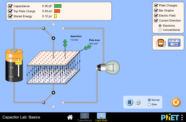 |
Explore how a capacitor works! Change the size of the plates and the distance between them. Change the voltage and see charges build up on the plates. View the electric field, and measure the voltage. Connect a charged capacitor to a light bulb and observe a discharging RC circuit. |
| Capacitor Lab |
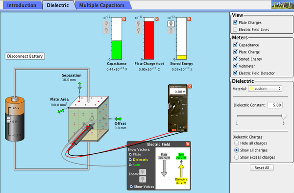 |
Explore how a capacitor works! Change the size of the plates and add a dielectric to see how it affects capacitance. Change the voltage and see charges built up on the plates. Shows the electric field in the capacitor. Measure voltage and electric field. |
| Parallel-Plate Capacitor |
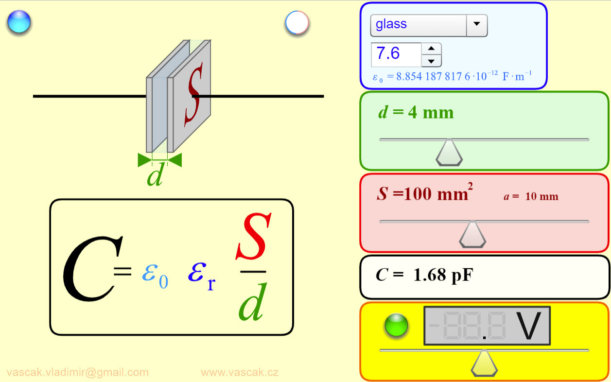 |
Great applet that shows you how the capacitance of a parallel-pplate capacitor changes you vary the plate area, separation, and dielectric. |
| RC Circuit | 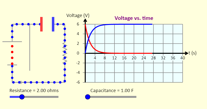 |
This is a simulation of a resistor-capacitor series circuit, involving a resistor, a capacitor, a battery, and a switch. Note that on the voltage graph, the red line shows the voltage across the resistor, and the blue line shows the voltage across the capacitor. The sliders allow you to adjust the values of the resistance and the capacitance. What is the largest current that can be achieved? What is the smallest current? You also have buttons to move the switch from one position to the other, either including the battery in the circuit or removing the battery from the circuit. There is another set of buttons to change the view from actual charge flow (red = positive, blue = negative) to conventional current (all charges flowing are positive). |
| Power Boxes - RC Circuit | 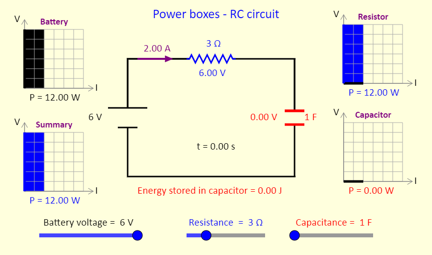 |
This simulation shows power boxes for a series RC circuit. The concept of power boxes was introduced in a September 2018 article in The Physics Teacher, by Daryl McPadden, Jason Dowd, and Eric Brewe, titled "Power Boxes: New Representation for Analyzing DC Circuits". This simulation shows the power boxes for a circuit with a resistor in series with a capacitor. The capacitor is initially uncharged. At the top left, the black region on the power box shows the power input to the circuit by the battery. On the right, we see (individually) the power dissipated as thermal energy and/or light by the resistor / light bulb and the power that is adding to the stored energy in the capacitor. Note the thick black line at the bottom of the capacitor power box, to indicate that there is still a current in the bottom wire in the circuit, even though the voltage there is zero. The power box at the bottom left is a summary for the circuit, showing an overview of the power in the circuit. Adjust the sliders, to see the impact on the power boxes of adjusting the battery voltage, the resistance, and the capacitance. |
| RLC Circuit | 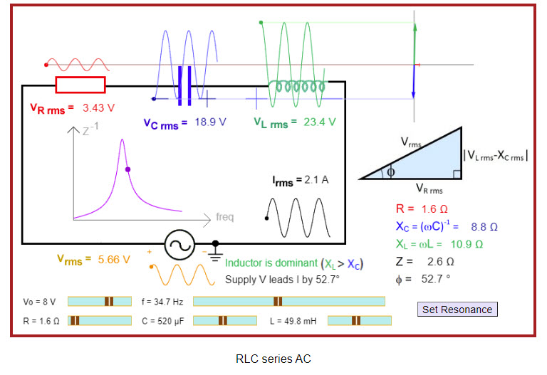 |
Great applet showing various aspects of a series RLC circuit. |
| RMS Voltage | 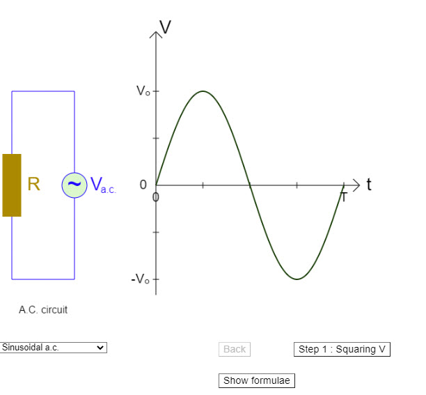 |
Nice simulation showing how RMS voltage is calculated. |