

Student Learning Objectives
Lessons / Lecture Notes
Important Equations
Example Problems
Applets and Animations
Student Learning Objectives
Lessons / Lecture Notes
PY106 Notes from Boston University (algebra-based):
Physics 2B notes from Dr. Bobby W.S. Lau (algebra-based)
HyperPhysics (calculus-based)
Physics 4B notes from Dr. Bobby W.S. Lau (calculus-based)
Important Equations (for algebra-based Physics)
|
|
|
Example Problems
Example Problems for algebra-based physics (from College Physics 2nd Edition by Knight, Jones, and Field):
Example Problems (Magnetic Induction and Lenz's Law)
Solutions to Example Problems (Magnetic Induction and Lenz's Law)
Example Problems for calculus-based physics (from Fundamentals of Physics 9th Edition by Halliday, Resnick, and Walker):
Example Problems (Induction and Inductance) | Example Problems (EM Oscillations and AC)
Solutions to Example Problems (Induction and Inductance) | Solutions to Example Problems (EM Oscillations and AC)
| Faraday's Law |
 |
Investigate Faraday's law and how a changing magnetic flux can produce a flow of electricity! |
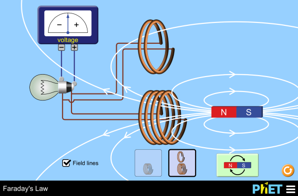
| Faraday's Electromagnetic Lab | 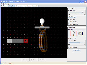 |
Play with a bar magnet and coils to learn about Faraday's law. Move a bar magnet near one or two coils to make a light bulb glow. View the magnetic field lines. A meter shows the direction and magnitude of the current. View the magnetic field lines or use a meter to show the direction and magnitude of the current. You can also play with electromagnets, generators and transformers! |
| Electromagnetic Induction |
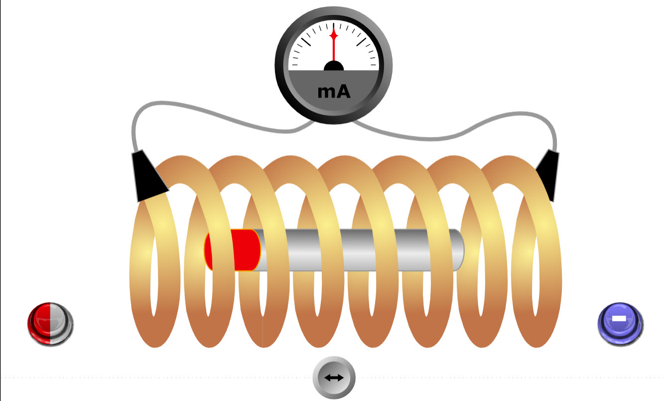 |
This simple animation shows the current induced in a coil when a magnet is moved near the coil. |
| Generator |
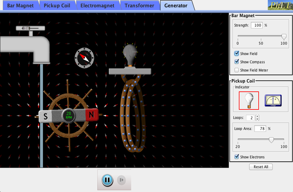 |
Generate electricity with a bar magnet! Discover the physics behind the phenomena by exploring magnets and how you can use them to make a bulb light. |
| Electric Motor |
 |
Nice applet showing how an electric motor works. |
| Generator |
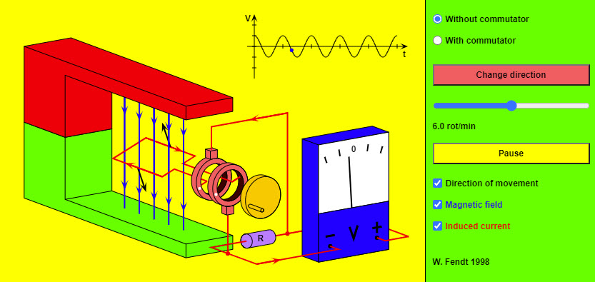 |
This HTML5 app simulates a generator which is reduced to the most important parts for clarity. Instead of an armature with many windings and iron nucleus there is only a single rectangular conductor loop; the axis the loop rotates on is omitted. The radio buttons in the top right corner allow you to choose an AC generator (without commutator), or a DC generator (with commutator). You can change the direction of rotation by using the corresponding button. The sliding control makes it possible to vary the rotational speed. You can stop and continue the simulation with the button "Pause / Resume". This, however, does not mean a real stop of the movement, for in this case the induced voltage would be reduced to zero. Two black arrows mark the momentary direction of movement. You can recognize the magnetic field lines (directed from the red painted north pole to the green painted south pole) by the blue color. The red arrows represent the direction of the induced current (conventional direction of current). |
| DC Electric Motor |
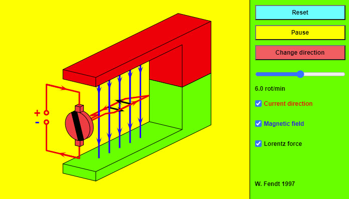 |
This HTML 5 app shows a direct current electrical motor which is reduced to the most important parts for clarity. Instead of an armature with many windings and iron nucleus there is only a single rectangular conductor loop; the axis the loop rotates on is omitted. The red arrows indicate the conventional direction of current (from plus to minus). You can recognize the magnetic field lines (directed from the red painted north pole to the green painted south pole) by the blue color. The black arrows represent the Lorentz force which is exerted on a current-carrying conductor in the magnetic field. The mentioned Lorentz force is perpendicular to the direction of current and to the magnetic field lines. The orientation of this force results from the well-known three finger rule (for the right hand!): |
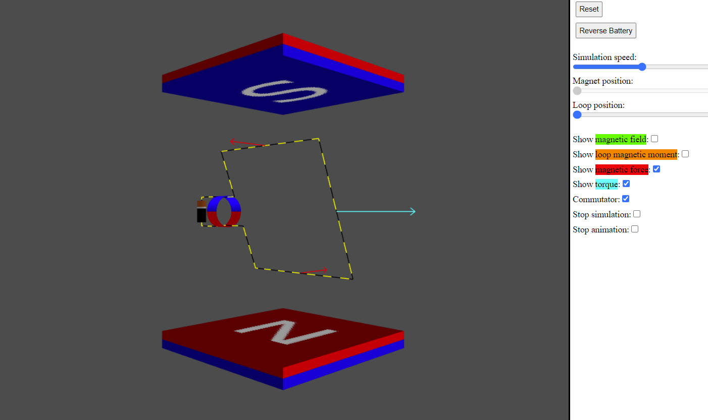
| DC Motor |
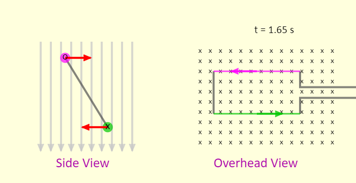 |
This is a simulation of direct current motor, which is simply a current loop that rotates in a magnetic field because of the torque applied to the loop by the field. The simulation shows two perspectives, a side view and an overhead view. The side view is the perspective when looking at the left side of the loop in the overhead view. To keep the torque going the same way on the loop, the current in the loop must be reversed every half rotation of the loop. The red arrows on the side view show the magnetic force applied to two sides of the loop. The purple and green arrows on the overhead view, and the x and o on the side view, indicate the current direction in those sides of the loop. |
| Electric Generator | 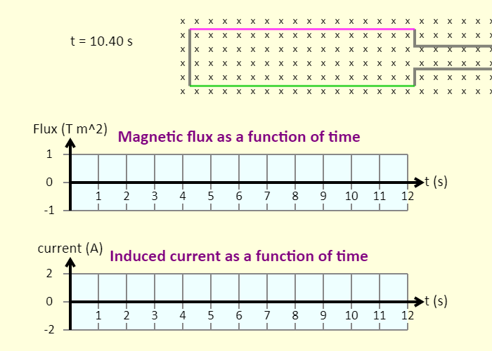 |
This is a simulation of an electric generator, which at its heart is simply a conducting loop rotating in a magnetic field. In this case the field is uniform and directed into the page. First, look at the rotating loop and predict what the graph of magnetic flux through the loop as a function of time will look like. See if you're correct. Then, predict what the graph of induced current as a function of time will look like. Again, see if you're correct. Finally, predict how the graphs will change when the loop rotates twice as fast. Again, check your prediction against the graph shown in the simulation. |
| Magnet and Loop | 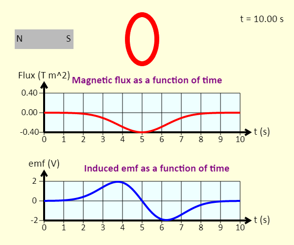 |
Watch a magnet pass through a coil at constant velocity. The graphs show the magnetic flux through each loop of the coil, as a function of time, as well as the emf induced in the coil as a function of time. |
| Magnet and Loop | 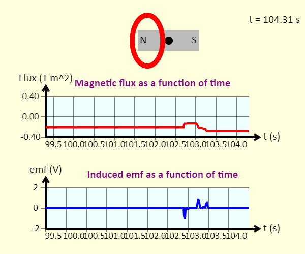 |
Click and drag the dot at the center of the magnet to move the magnet left or right. The graphs show the magnetic flux through each loop of the coil, as a function of time, as well as the emf induced in the coil as a function of time. |
| Motional EMF | 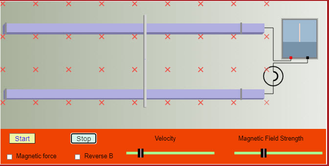 |
This applet shows how a motional emf is generated. |
| Motional EMF | 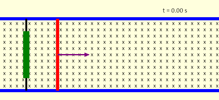 |
This is a simulation of motional emf. The red rod can slide without friction on the blue rails. A constant force (in red) is applied on the rod to the right. We might think that that would result in motion with constant acceleration to the right, but that's not what we see. One key is that there is a uniform magnetic field directed into the screen. As time goes by, we see that a resistive force (in orange) to the left gradually builds up, until the rod reaches a constant velocity. We call this a terminal velocity. The resistive force come about because the rod, rails, and the green resistor and black wires on the left make up a complete conducting circuit. Moving the rod to the right increases the magnetic flux through that loop, giving rise to an induced current in the loop that acts to oppose whatever is making the flux change. The current experiences a force because of the field - this is the resistive force that acts against the motion of the rod. The applied force is removed after 8 seconds - what happens then? |
| Loop and Field | 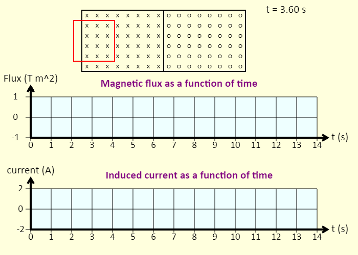 |
Watch a loop pass through a region of magnetic field. Note that the magnetic field is directed into the screen on the left side, and out of the screen on the right side. Predict what the graphs will look like before you view them. The graphs show the magnetic flux (positive when the field lines are into the screen) through the loop, as a function of time, as well as the current induced in the loop as a function of time. |
| Electromagnetic Railgun | 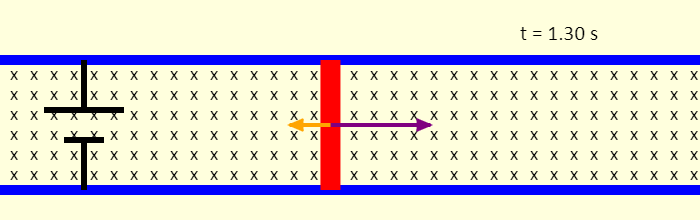 |
This is a simulation of an electromagnetic railgun. The red projectile can slide without friction on the blue rails. The battery causes a current to flow around the loop consisting of the battery, rails, and the projectile. The current directed down through the projectile, in the uniform magnetic field directed into the page, gives a force on the projectile directed right - this accelerates the projectile to the right. The motion of the projectile increases the magnetic flux through the loop. This gives rise to an induced current in the opposite direction of the current from the battery, and an associated resistive force that acts on the projectile. The faster the projectile goes, the larger the rate of change of flux, the larger the induced current, and the larger the resistive force. Eventually, the resistive force matches the force to the right. The forces balance, and the projectile moves at constant velocity after that. The velocity can be impressively large, however! |
| Lenz's Law |  |
Nice animation showing Lenz's Law. |
| Electromagnetic Oscillating Circuit | 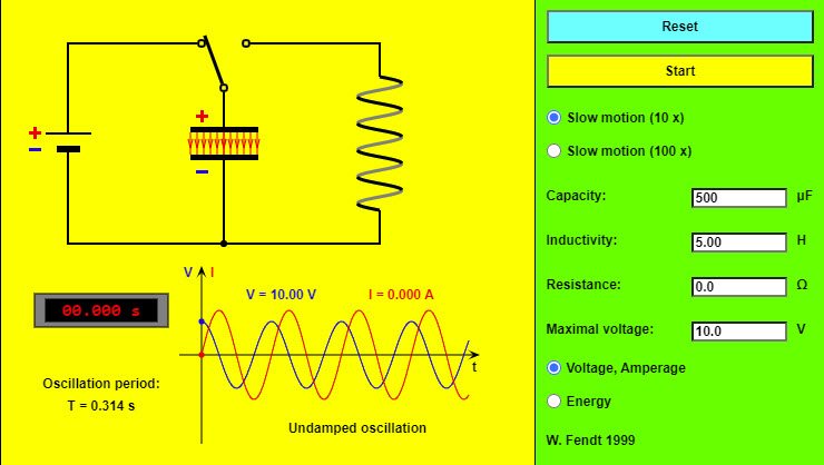 |
This simulation deals with an electromagnetic oscillating circuit, consisting of a capacitor (center) and an inductor (i.e. a coil, on the right). As soon as you have pressed the "Reset" button, the plates of the capacitor will be charged, namely the upper plate positively and the lower plate negatively. After clicking on the "Start" button with the mouse, the switch will be brought to its other position so that the oscillation will begin. The same button makes it possible to interrupt respectively resume the simulation. The animation will be 10 or 100 times slower than the real oscillation, depending on the selected radio button. You can vary the values of the capacity (from 100 μF to 1000 μF), the coil's inductivity (from 1 H to 10 H) and resistance (from 0 Ω to 1000 Ω) and the voltage of the battery by using the four text fields. The electric field of the capacitor (red) and the magnetic field of the inductor (blue) are indicated by field lines in the circuit diagram. The density of these field lines shows the strength of the corresponding field. In addition, you can see the charge signs of the two capacitor plates and arrows for the (conventional) current direction. At the left bottom a digital clock indicates the time since the begin of the oscillation; under there you can read the oscillation period. At the right bottom one of two diagrams is to be seen, depending on the selected radio button in the lower part of the control panel: |
| Simple AC Circuits | 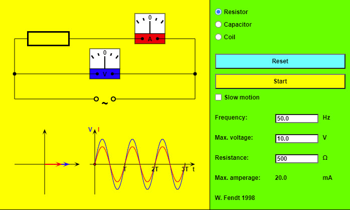 |
This HTML5 app shows a simple circuit consisting of an alternating voltage source and, depending on the selected radio button, a resistor (without inductivity), a capacitor or an ideal coil (without resistance). In addition there are meters for the voltage V (blue) and the amperage I (red). Below the drawing of the circuit you see on the left a phasor diagram; it is possible to read the momentary oscillation phases from the position of the two phasors (voltage blue, amperage red). The projection of a phasor onto the vertical axis corresponds to the momentary value of V respectively I. On the bottom right the dependence of voltage and amperage on the time is illustrated in a diagram. The "Reset" button brings the circuit to its initial state. You can start or stop and continue the simulation with the other button. If you choose the option "Slow motion", the movement will be ten times slower. It is possible to vary the preselected values of frequency, maximal voltage and resistance respectively capacity or inductivity. The program will indicate the new value of the maximal amperage. |
| RLC Impedance Triangle | 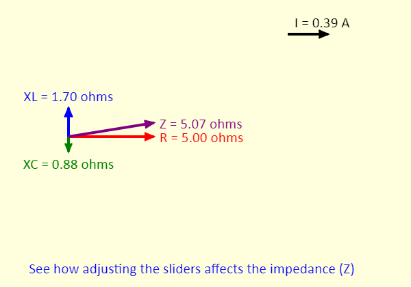 |
This simulation shows the impedance triangle for a series RLC circuit. The impedance (Z) of the circuit is the hypotenuse of the triangle. The resistance is the horizontal side of the triangle. The vertical side is the sum of the inductive reactance (XL, in the positive y direction) and the capacitive reactance (XC, in the negative y direction) vectors.
|
| RLC Circuit | 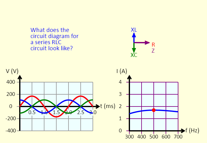 |
This simulation shows several representations for a series RLC circuit. The impedance triangle is shown at the top right. At the bottom left is the voltage vs. time graph, for the source voltage (purple), the voltage across the resistor (red), the voltage across the inductor (blue), and the voltage across the capacitor (green). At the bottom right is a graph of the peak current as a function of the frequency. Adjust the sliders, and see what changes in response. |
| RLC AC Circuit | 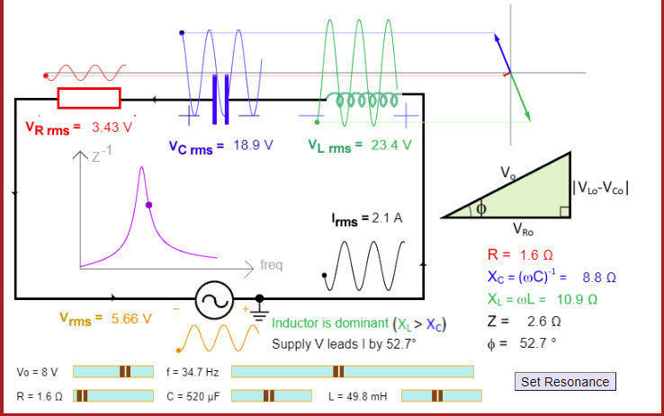 |
This excellent applet shows a series RLC circuit and allows you to change the resistance, capacitance, and inductance of the circuit. |
| Simple AC Circuits | 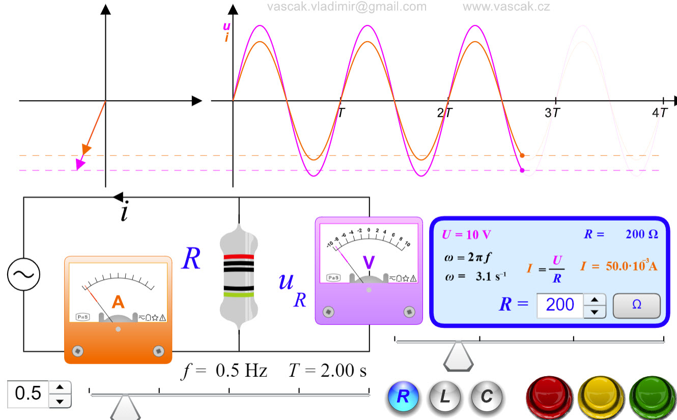 |
A nice animation showing the three simple AC circuits. |
| Combinations of Resistors, Inductors and Capacitors | 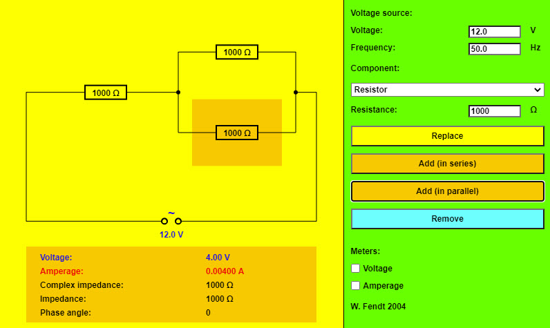 |
A nice applet that allows you to build circuits with combinations of resistors, inductors, and capacitors in series and parallel. |